I made a load cell for my undergraduate degree project and my Master’s research. Essentially, a load cell is a device that measures a force applied to it. The way they do this varies from device to device but for the most part, they work by acting as springs with you measuring how much they are compressed or stretched. You measure this compression or stretching, known as deformation in engineer speak, with things called strain gauges. Strain gauges themselves are a deep topic, but the most common one in use is the electrical resistance based strain gauge. Basically, this gauge measures deformation by measuring its change in resistance. Now, to get the force applied to the load cell from all this, you use Hooke’s Law. Hooke’s law relates the deformation proportionally to the amount of force is applied, and is dependent on the material you use for the load cell. And that’s basically how load cells work.
The load cell my project partner Daniel Eagan and I made works in the same manner, apart from one major difference. Instead of using a strain gauge based on the change of electrical resistance to measure the deformation, we use a fiber optic sensor called a fiber Bragg grating. Wait, what? Yep, now we’re in optics. A fiber Bragg grating, or FBG for short, is a series of burn marks in a fiber optic cable that reflect a particular wavelength of light when shined upon with a white light (as in the white light is shined down the cable, not at it from the outside!). This reflected wavelength changes proportionally to the amount of deformation the FBG feels. So again, we measure the deformation and use Hooke’s law to get the force but now we’re just using a different way to measure the deformation. This is what we did for our undergraduate project in mechanical engineering.
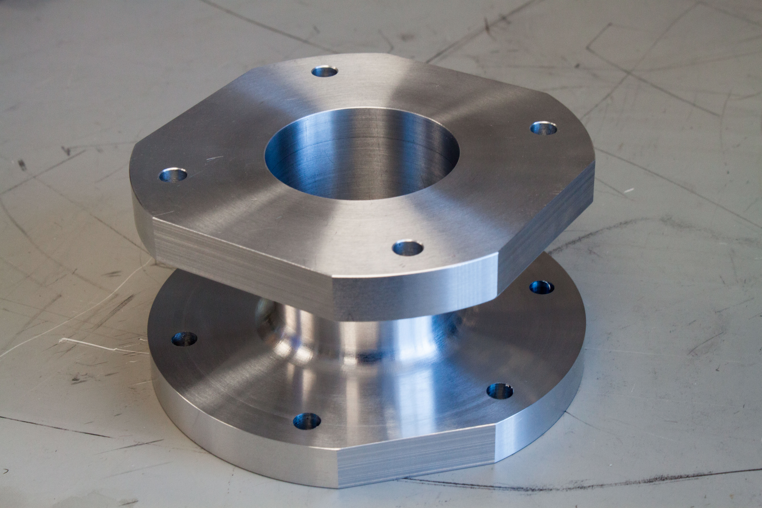
Here’s what it looked like:
and here’s a video:
and a demo:
Why did we do this? We did this because electric motors are starting to find their way into aviation and NASA has been playing with them to determine their capabilities for flight. When you are just starting to investigate propulsion devices for flight, you do a lot of ground testing. And one thing in this ground testing is determining how much thrust, which is a force, is produced by the propulsion device. So they use load cells to measure the thrust. Now, a problem arises with electrical motors when you do this. They produce a lot of electromagnetic interference, or EMI, because… magic. Think of antennas, they intentionally radiate and receive electromagnetic waves, such as radio waves. When these waves are unwanted, it’s called EMI. Guess what, EVERY electrical circuit acts like an antenna. Part of the FCC’s job in the USA is make sure electrical products properly mitigate this so that everything plays nice with each other in the electronics world. It’s kind of an issue. So when you take the electrical motor’s EMI into account and realize those electrical resistance based strain gauges are fundamentally used in an electrical circuit to work… well they just can’t avoid the EMI. The result is the force data you get when doing ground testing, using load cells based on this tech, is trash. FBG’s don’t have this problem; they don’t use an electrical circuit to work. Hence, you get clean data.
My Master’s research was to prove experimentally this is true. The videos below show some of the tests I ran:
Spoiler: the experiments backed up the reasoning. Here’s my publication on it: